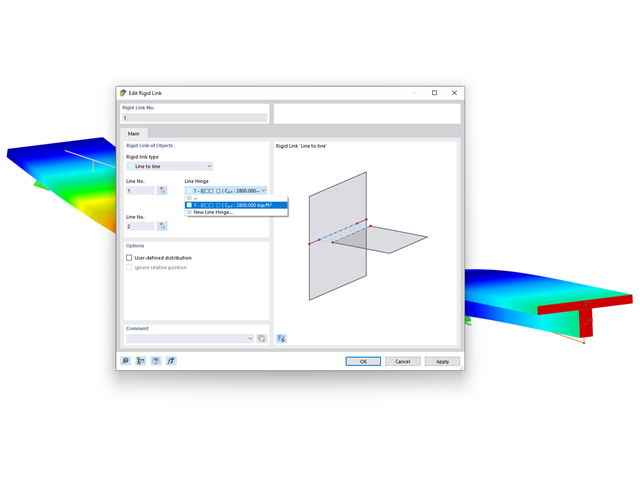
For rigid links, it is possible to define line hinges. This allows for semi-rigid coupling of different elements, for example.

Do you want to determine the biaxial bending resistance of a reinforced concrete cross-section? For this, you have to activate a moment-moment interaction diagram (My-Mz diagram) first. This My-Mz diagram represents a horizontal section through the three-dimensional diagram for the specified axial force N. Due to the coupling to the 3D interaction diagram, you can also visualize the section plane there.
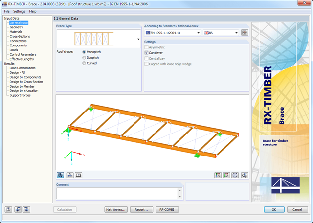
The geometry is entered by means of templates, as in all other programs of the RX‑TIMBER family. By selecting the roof structure, you define the base geometry, which can be adjusted by user-defined settings. The relevant timber grade of the material can be selected from the material library. All material grades for glulam, hardwood, poplar and softwood timber specified in EN 1995-1-1 are available. Furthermore, it is possible to generate a strength class with user-defined material properties in order to extend the library.
Since the stiffening bracing includes the steel cross-sections, current steel grades are integrated in the library as well. Therefore, rolled and welded cross-sections are also available. Stiffening of coupling elements can be considered in Table 1.5 Connections as translational and rotational spring stiffnesses. The program handles these stiffnesses with a stiffness divided by the partial safety factor for the design of the bearing capacity and with the mean values of the stiffness for the serviceability limit state design. The loading can be entered directly as a lateral load (equivalent lateral load) resulting from a truss girder design.
The wind load is applied automatically to all four sides of the structure. Additionally, you can specify user-defined loads; for example, concentrated loads from columns (buckling load). According to the generated loads, the program automatically creates combinations for the ultimate and serviceability limit states as well as for fire resistance design in the background. The generated combinations can be considered or adjusted by user-defined specifications.
- General stress analysis
- Graphical and numerical results of stresses and stress ratios fully integrated in RFEM
- Flexible design with different layer compositions
- High efficiency due to few entries required
- Flexibility due to detailed setting options for basis and extent of calculations
- A local overall stiffness matrix of the surface in RFEM is generated on the basis of the selected material model and the layers contained. The following material models are available:
- Orthotropic
- Isotropic
- User-defined
- Hybrid (for combinations of material models)
- Option to save frequently used layer structures in a database
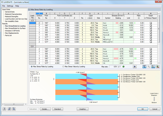
- Determination of basic, shear, and equivalent stresses
- In addition to the basic stresses, the required stresses according to DIN EN 1995-1-1 and the interaction of those stresses are available as results.
- Stress analysis for structural surfaces including simple or complex shapes
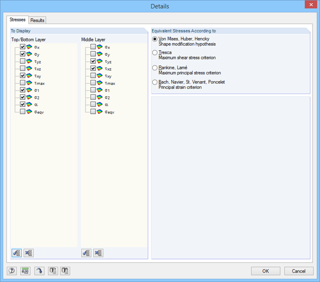
- Equivalent stresses calculated according to different approaches:
- Shape modification hypothesis (von Mises)
- Shear stress hypothesis (Tresca)
- Normal stress hypothesis (Rankine)
- Principal strain hypothesis (Bach)
- Calculation of transversal shear stresses according to Mindlin or Kirchhoff, or user-defined specifications
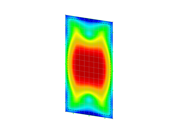
- Serviceability limit state design by checking surface displacements
- User-defined specifications of limit deflections
- Possibility to consider layer coupling
- Detailed results of individual stress components and ratios in tables and graphics
- Results of stresses for each layer in the model
- Parts list of designed surfaces
- Possible coupling of layers entirely without shear
The global calculation assigns the stiffness determined by means of the selected composition and the glass geometry to each surface. Then, the calculation proceeds using the plate theory. It is possible to select whether the shear coupling of layers should be considered.
In the case of the local calculation, you can further specify 2D or 3D calculation. Two-dimensional calculation means that the single-layer or laminated glass is modeled as a surface, whose thickness is calculated on the basis of the selected structure and glass geometry (using the plate theory). Similarly to the global calculation, you can optionally consider shear coupling of layers.
The 3D calculation uses solids in the model to substitute each composition layer. This way, the results are more accurate, but the calculation may take more time.
It is possible to model insulating glass only if local calculation is selected. The gas layer is always modeled as a solid element, so it is necessary to design individual insulating glass parts independently of the surrounding structure. The ideal gas law (thermal equation of state of ideal gases) is considered for the calculation and the third-order analysis.
- Design of single-layer or laminated glass as well as gas layer insulating glass
- design of curved glass
- Option to select either local calculation without regard to the influence of a surrounding structure, or global calculation with regard to the influence of an entire structure
- Calculation of limit stresses according to DIN 18008:2010-12 or TRLV:2006-08
- Assignment of loads to load duration classes
- Extensive material library including all common glass, foil, and gas types in compliance with the DIN 18008:2010-12, E DIN EN 13474 standards, and the TRLV:2006-08 regulation
- Optional consideration of shear coupling of layers
- Consideration of climatic loads
- Calculation according to the linear static analysis or nonlinear analysis according to the large deformation analysis. analysis
- Stress analysis, ultimate limit state design, serviceability limit state design
- Graphical representation of all results in RFEM
- Possibility to filter results and color scales in result tables
- Direct data export to MS Excel
There are various options available for beam modeling. A roof type determines the exact purlin location for wind and snow generation.
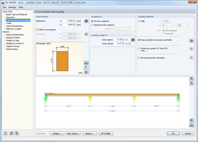
Two beam types are available: continuous beam and purlin. If you select the continuous beam, it is possible to define several hinge conditions of the beam. If you select the purlin, it is not possible to modify hinge conditions. In this case, the calculation considers a double cross-section in the coupling zone. In addition, several coupling elements are available in the purlin settings:
- Nails (prebored/not prebored)
- Ring and plate connectors and bolts
- Screw connection with fastening system WT from SFS intec
- User-defined specification using characteristic strength
The relevant timber grade of the material can be selected from the material library. All material grades for glulam, hardwood and softwood timber specified in EC 5 are available. Furthermore, you have the option to generate a strength class with user-defined material properties and thus extend the library.A comprehensive and extensible material library can also be used for entering permanent loads (for example, roof structure).
Generators integrated in RX-TIMBER Purlin allow for convenient generation of various wind and snow load cases. By clicking the information buttons, the map of wind and snow zones for the relevant country is displayed. The corresponding zone can be selected with a double-click. Load cases can be checked graphically.
However, you can enter load specifications manually as well. According to the generated loads, the program automatically creates combinations for the ultimate and serviceability limit states as well as for fire resistance design in the background.